What can happen when you do this?
- Does the distribution of suction cups on a 2-circuit vacuum lifter signify anything in particular?
- What impact can a change in suction cup arrangement have?
- Are there any grounds for concern about this?
- So everything is fine then. The suspended load is held in place by the vacuum lifter.
Why should you pay attention to the correct distribution of suction cups?
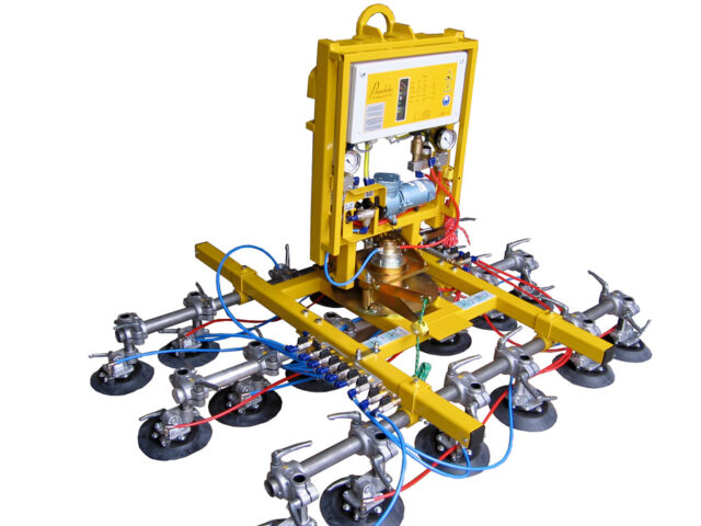
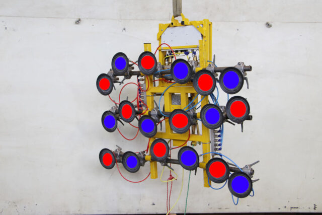
The vacuum circuits were distributed almost uniformly across the entire surface area.
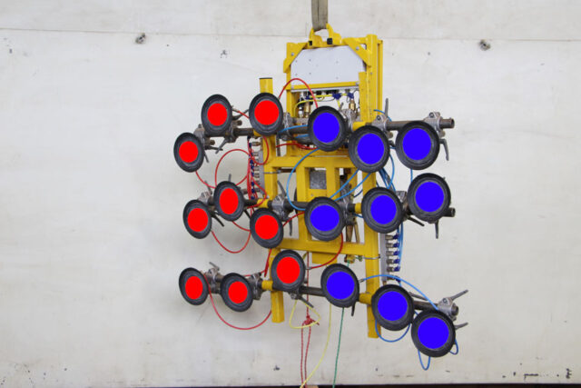
There was one vacuum circuit on the right side and the other vacuum circuit was on the left side. That way, uniform load distribution is not possible!
Perhaps more thought should be given to this!
Even if this all went fine, without any problems, you should still have a think about this particular application. Does the arrangement of suction cups really not have a role to play?
Why should a 2-circuit vacuum lifter be used on construction sites?
Every vacuum lifter has a defined safe working load. If the vacuum lifter is overloaded, it detaches from the material being transported. You should bear this in mind when considering a practical application.
It is not all that easy to calculate actual load distribution characteristics. Which is why we are now going to take a look at this in broadly simplified terms.
Is there really a benefit to having a 2-circuit device?
It is therefore assumed that it is not possible on construction sites to ensure that loads are not being lifted above people. For this reason, the vacuum lifter needs to be safer. Two independent vacuum systems need to be present. If one vacuum system fails, the remaining vacuum system should be capable of holding double the nominal load rating as a safety measure.
This means that, if a device is designed for loads of 500 kg, and if it has two vacuum circuits, each vacuum circuit needs to be able to hold a test load of 1000 kg safely. Based on our understanding of EU standard EN 13155, this needs to be assured for at least 5 minutes, and in any position.
Can that still work when vacuum circuits are distributed in such a one-sided way?
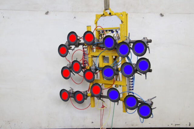
That will not work because the suction cups not only need to hold the actual weight of the load but also to hold part of the load weight that acts on the suction cups by lever arm action.
Let us assume that the weight of this plate is distributed uniformly across the entire surface area.If the plate measures 4 metres in length, 2 metres in width and weighs 500 kg, the load could be divided into sections, each 1 metre in length. Each section could then be assumed to represent 125 kg, applied centrally on each one-metre section.
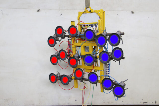

In other words, the suction cups in the blue circle are subjected to a load weight of approximately 250 kg, or 125 kg for those subjected to a lever arm of 1.5 m and 125 kg [sic] for those with a lever arm of 2.5 m.
As stated, this only applies if a circuit fails and is barely noticed in the normal application. However, a 2-circuit device should of course provide greater safety in the event of one vacuum circuit failing.
In the original arrangement of suction cups, the forces to be absorbed are distributed more evenly across the entire suction cup frame. In any event, the manufacturer should distribute them in such a way that individual suction cups do not get overloaded.
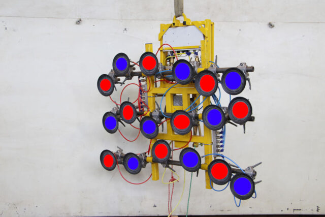

For this reason, never alter this distribution if you wish to avoid impairing device safety, and of releasing the manufacturer from his obligations.
If you would like to see the impact of this on the vacuum lifter shown here during maintenance work on our premises, please just take another look at this video. Perhaps seeing it will carry more conviction for you than the written word.
If you do not already know the impact of a lever arm of this kind, then you should perhaps test this for yourself:
Take a sledgehammer weighing 5 kg. Hold the shaft of the hammer directly behind the weight then extend your arm. Generally speaking, that is quite easy to accomplish. Now grip the shaft of the hammer at its other end, and now try to lift the hammer into a horizontal position with your arm extended. Are you now aware of what a difference that makes?
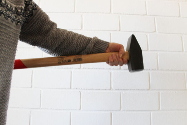
“A short hammer on an outstretched arm”
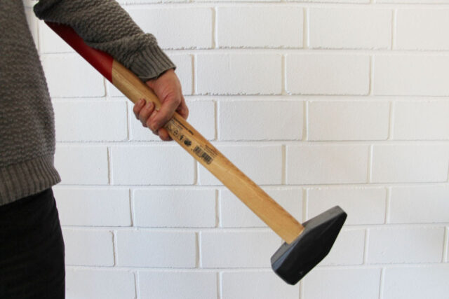
“An attempt to lift the hammer with an outstretched arm, gripping the shaft at its halfway point”
This is a quick and simple way of demonstrating the effect of a lever arm.
Mind you, there are some manufacturers of vacuum lifters who are not familiar with the objective of having a 2-circuit device, or who have not considered this kind of implementation accurately. Therefore, whenever you purchase a vacuum lifter, you should also check that the suction cups are arranged in this way if you wish to have a safe device.
Here is another example that occurred to us during the maintenance of a vacuum lifter.
Results of the load test (with new suction cups)
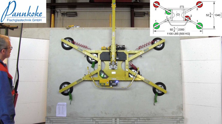
Vertical load scenario
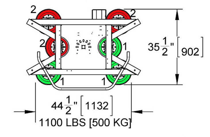 |
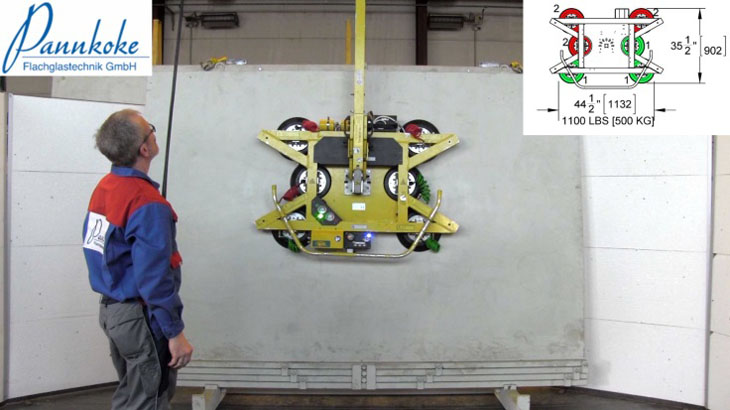
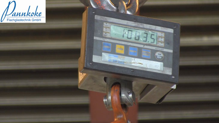
This configuration level should be able to move loads of 500 kg. This means that one vacuum circuit should be able to hold loads of 1000 kg.
This is also satisfied during the first few seconds, although on a declining trend, during the first 60 seconds. |
 |
 |
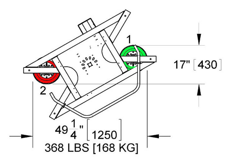 |
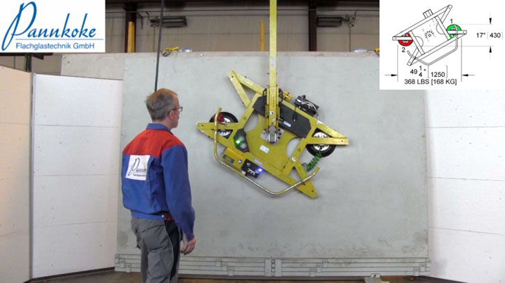
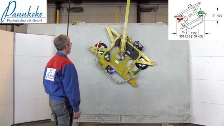
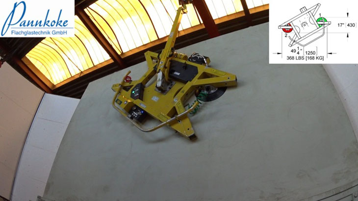
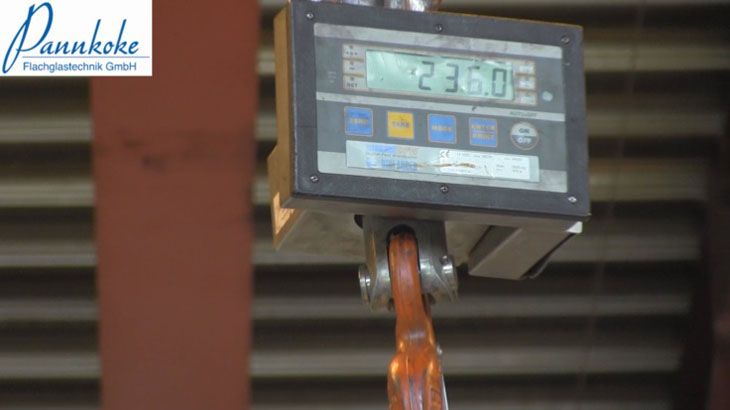
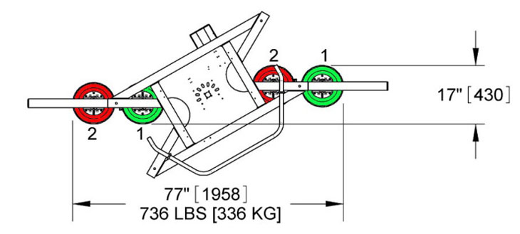
This configuration level should be able to move loads of 168 kg. This means that one vacuum circuit should be able to hold loads of 336 kg.
This is not achieved. The device rotates around the suction cup. The crane scale indicates 236 kg after the first few seconds. |
 |
 |
 |
 |
 |
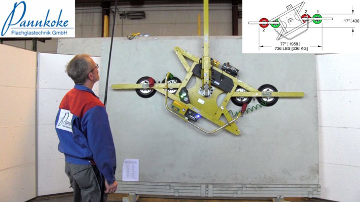
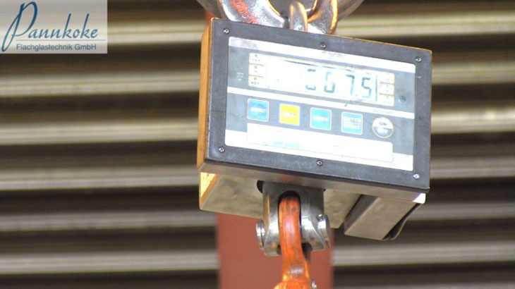
This configuration level should be able to move loads of 336 kg. This means that one vacuum circuit should be able to hold loads of 672 kg.
This is also satisfied during the first few seconds, although on a declining trend, during the first 60 seconds. |
 |
 |
 |
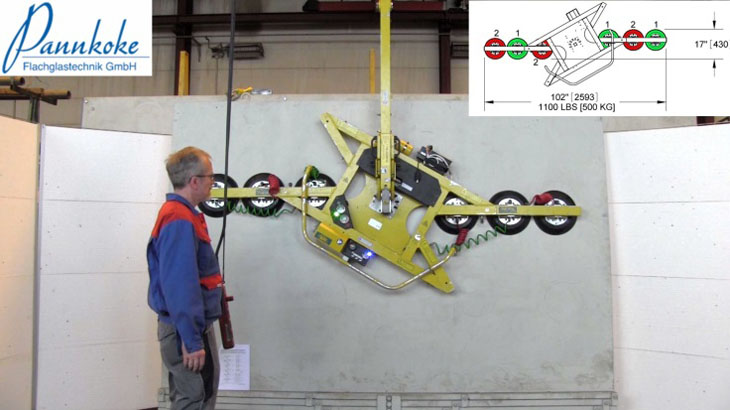
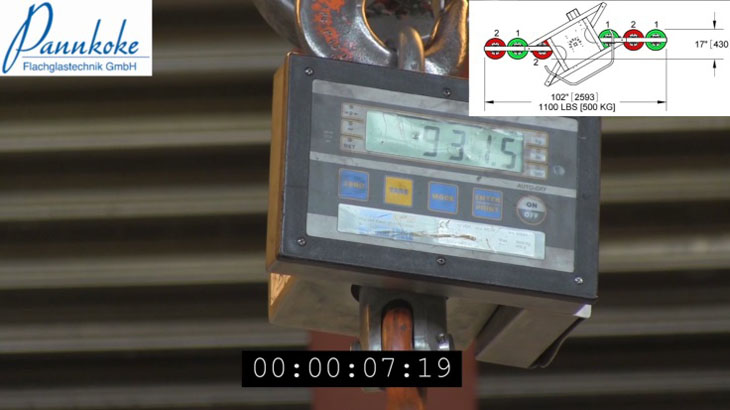
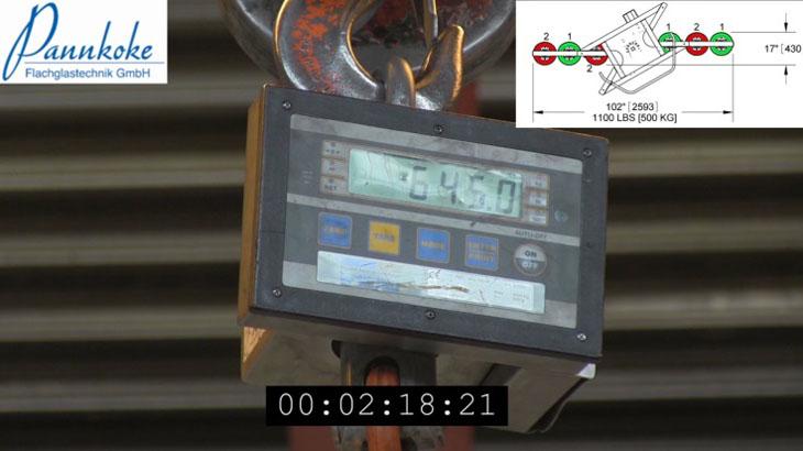
This configuration level should be able to move loads of 500 kg. This means that one vacuum circuit should be able to hold loads of 1000 kg.
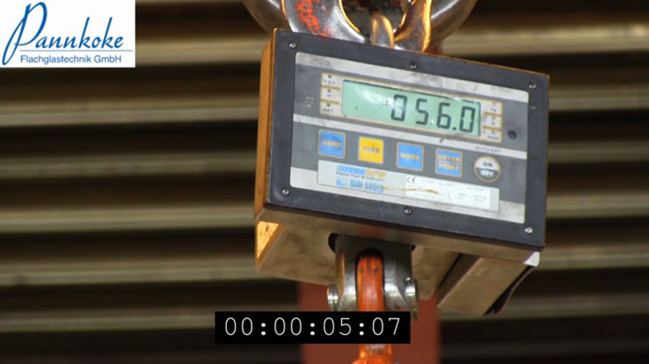
This is also scarcely reached at the start. It begins at approx. 930 kg then declines over the next 2 minutes to 645 kg, then continues to decline. After this time the test was interrupted. |
 |
 |
 |
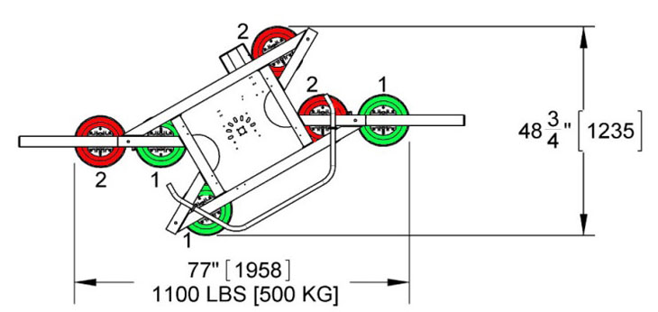 |
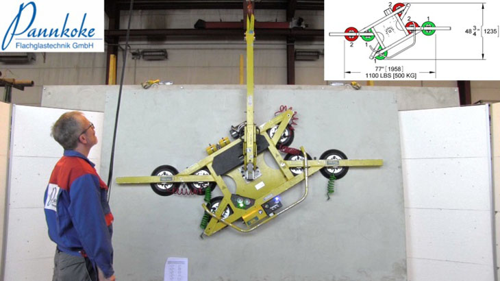
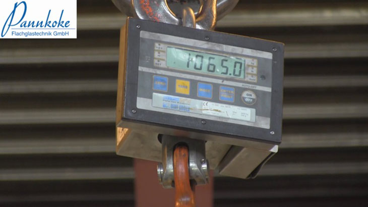
This configuration level should be able to move loads of 500 kg. This means that one vacuum circuit should be able to hold loads of 1000 kg.
This is also satisfied during the first few seconds, although on a declining trend, during the first 60 seconds. |
 |
 |
 |
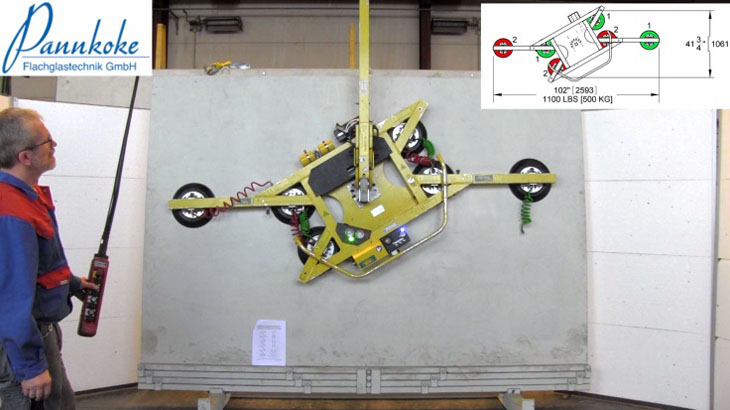
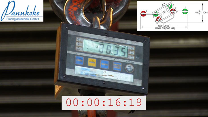
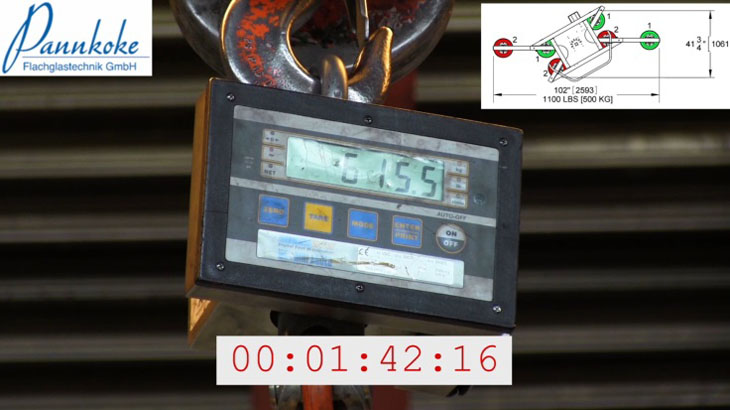
This configuration level should be able to move loads of 500 kg. This means that one vacuum circuit should be able to hold loads of 1000 kg.
This is also scarcely reached at the start. It begins at approx. 860 kg then declines over the next 1.7 minutes to 615 kg, then continues to decline. After this time the test was interrupted. |
 |
 |
 |
 |
This configuration level should be able to move loads of 500 kg. This means that one vacuum circuit should be able to hold loads of 1000 kg.
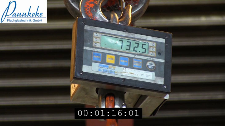
This is also scarcely reached at the start. It begins at approx. 860 kg then declines over the next 1 minute to 730 kg, then continues to decline. After this time the test was interrupted. |
 |
 |
 |
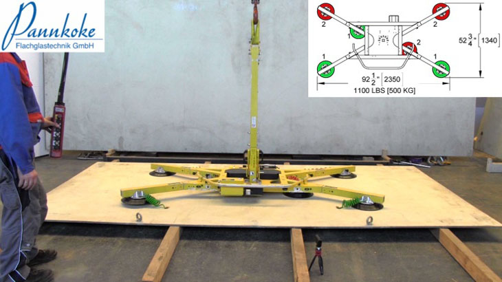
Horizontal load scenario
 |
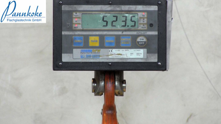
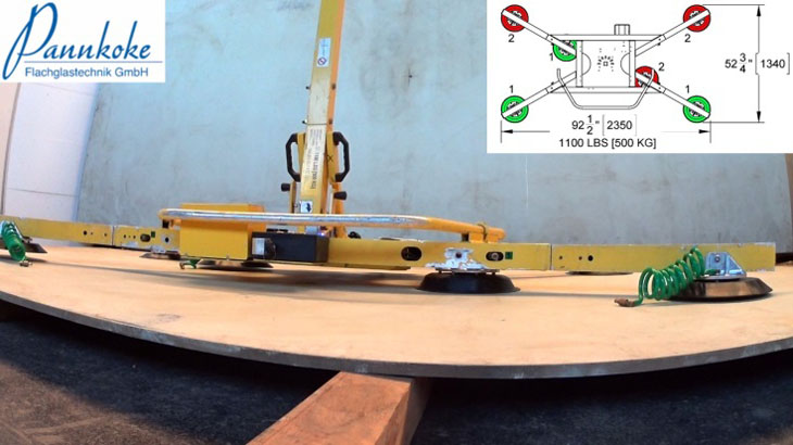
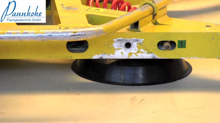
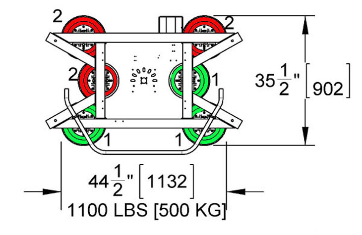
This configuration level should be able to move loads of 500 kg. This means that one vacuum circuit should be able to hold loads of 1000 kg.
At approx. 520 kg, the suction cup is in a very dubious condition. Any additional load would cause the suction cup to become detached. This approach is not able to reach the specified 1000 kg. |
 |
 |
 |
 |
 |
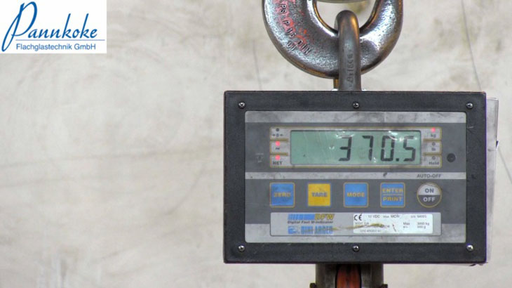
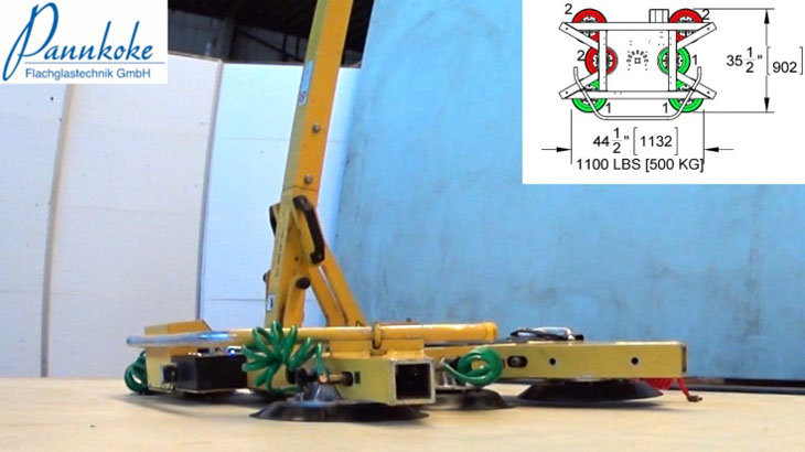
This configuration level should be able to move loads of 500 kg. This means that one vacuum circuit should be able to hold loads of 1000 kg.
At approx. 370 kg, the suction cup is in a very dubious condition. Any additional load would cause the suction cup to become detached. This approach is not able to reach the specified 1000 kg. |
 |
 |
 |
 |
There is video footage to document these written accounts of the tests conducted. This enables everyone to see how these tests were conducted. Here are the links to it:
Our advice
Always try to distribute the suction cups of each vacuum circuit across the surface area.
Never change the arrangement of suction cups into a configuration that is not specified by the manufacturer. The manufacturer needs to know how to design the device safely and in compliance with EU standard EN 13155.
If you wish, we can provide you with an appropriate training course on this subject.
It is much better to think carefully about things in advance than to go looking for an explanation after an accident has occurred.
Your personal safety and that of your payroll staff is at stake!
