What can happen when you do this?
- Would you also do it this way?
- Are there any grounds for concern about this?
- So everything is fine then. The suspended load is held in place by the vacuum lifter.
- Everything looks great. Do you have any concerns?

So sollte man es nicht machen.
Perhaps more thought should be given to this!
Even if this all went fine, without any problems, you should still have a think about this particular application. How is the load distributed across the vacuum lifter?
Every vacuum lifter has a defined safe working load. If the vacuum lifter is overloaded, it detaches from the material being transported. You should bear this in mind when considering a practical application.
It is not all that easy to calculate actual load distribution characteristics. Which is why we are now going to take a look at this in broadly simplified terms.
Simple format for considering load distribution
Let us assume that the weight of this strip is distributed uniformly across the entire surface area. If the strip measures 10 metres in length and weighs 1000 kg, the load could be divided into sections, each 1 metre in length. Each section could then be assumed to represent 100 kg, applied centrally on each one-metre section.

To lift that load horizontally, a vacuum lifter is used with the outer suction cups arranged at a distance of 6 metres.
If that vacuum lifter now applies its suction centrally, load distribution can be assumed to be symmetrical. However, always bear in mind that the outer suction cups are subjected to higher levels of load than the inner ones.
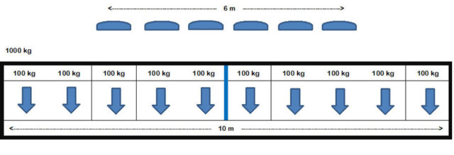
In this simplified scenario, the outer suction cups are subjected to their own 100 kg plus a further 100 kg, with a lever arm of 1 metre plus a further 100 kg, with a lever arm of 2 metres. This makes it possible to identify quickly that attention needs to be paid to correct load distribution.
To learn how this kind of lever arm manifests itself, just take a sledgehammer weighing 5 kg. Hold the shaft of the hammer directly behind the weight, then extend your arm. Generally speaking, that is quite easy to accomplish. Now grip the shaft of the hammer at its other end, and now try to lift the hammer into a horizontal position with your arm extended. Are you now aware of what a difference that makes?
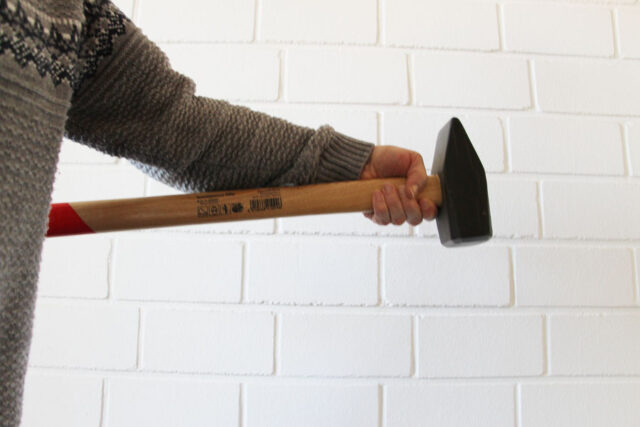
“A short hammer on an outstretched arm”
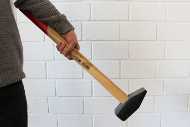
“An attempt to lift the hammer with an outstretched arm, gripping the shaft at its halfway point”
This is a quick and simple way of demonstrating the effect of a lever arm.
This symmetrical example already demonstrates clearly how vacuum lifters can get overloaded, even if they not even being required to lift their nominal weight.
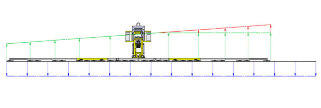
Now let us take another look, this time with an asymmetric distribution, one where suction is being applied by the vacuum lifting device in a one-sided manner.
In this simplified view, the outer suction cups are now being subjected to substantially higher forces than they were in the symmetrical load scenario. In addition to their own 100 kg, a further 100 kg is added, with a 1-metre lever arm as well as 100 kg with a lever arm of 2 metres, 100 kg with a lever arm of 3 metres and a further 100 kg with a lever arm of 4 metres. So even without considering the lever arm, in our simplified model, each of these outer suction cups is being required to lift 400 kg more than their inner counterparts.
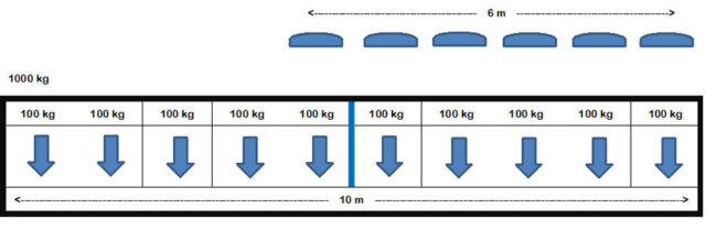
Now let us take a different look at the application illustrated here. The downward-facing blue arrows represent the weight load. The upward-facing arrows represent the carrying capacity being applied to the suction cups. Since vacuum lifting device should always be designed to cope with twice their load rating, this seems to make no difference in most applications. In particular on multi-circuit vacuum lifting devices. However, the built-in theoretical safety margin is sacrificed entirely in such cases and, if a fault occurs, there is then no back-up system in place. If too much force is involved, even in normal scenarios, there is a risk of overload occurring.
Our advice
Always try to distribute the load exerted on suction cups symmetrically.
If this is not possible, think about which forces may be applied to each suction cup, and incorporate the individual carrying capacity of a single vacuum cup in your considerations. If even just one suction cup gets overloaded, causing it to tear away from the load, this can rapidly lead to a chain reaction, causing the load to detach itself from the vacuum lifting device.
It is much better to think carefully about things in advance than to go looking for an explanation after an accident has occurred.
Your personal safety and that of your payroll staff is at stake!