Since 1 January 2004, EU construction sites or other hazardous locations have been obliged to use 2-circuit vacuum lifting devices. This is something that most people now know, but are you aware of what this actually signifies?
EU standard EN 13155 defines how a vacuum lifter in the EU must be constructed.
The main components in a vacuum lifter without its own suction capability are as follows:
- A support frame that transmits forces from suction cups to the crane hook.
- Vacuum generation to enable the suction cups to carry something.
- A non-return valve to maintain vacuum in the event of a failure of vacuum generation.
- A vacuum supply tank to balance out low levels of vacuum loss.
- A control valve to enable the operator to switch between SUCTION and RELEASE
- One or more suction cups to hold the load
To make things safer for users, a vacuum lifting device needs to have these items of warning equipment and notices:
- A vacuum meter to provide information about the danger area and the working area.
- A visual or acoustic warning device to warn of insufficient vacuum, one capable of continuing to function in the event of a power failure.
The 1-circuit vacuum lifter
A vacuum lifting device of this kind has what is known as a sealed vacuum circuit. Furthermore, suction cups need to be designed with the ability to carry twice the nominal load rating at all times. Here is an example to clarify what that means: A vacuum lifting device with a load rating of 500 kg must be capable of holding twice that nominal load rating of 500 kg in every conceivable position. Which means that the vacuum lifter needs to able to hold a load weighing 1000 kg, as specified in EU standard EN 13155. That is what it takes to provide users with a sufficient level of protection.
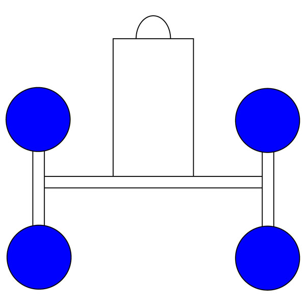
A single vacuum circuit, all 4 suction cups are marked here in blue.
If one vacuum circuit develops a leak, for example when a vacuum line gets severed, the load drops because the suction cups are no longer able to carry anything.
This was why members of the standards committee stipulated the need for a second vacuum circuit. For areas of higher risk, which is to say wherever people might be standing under suspended loads, this second vacuum circuit should be able to provide the same level of safety as the first one. Which in turn means that, if one vacuum circuit should fail, the other vacuum circuit should be able to support twice the nominal rating.
The 2-circuit vacuum lifter
This fact alone shows that a 2-circuit vacuum lifting device used on construction sites actually needs to have double the number of suction cups as its 1-circuit counterpart. Where the device is used in-company, which is to say in an area with a lower level of potential danger, all the suction cups count together once again. This is a design matter, based upon how the risk level is classified. Theoretically, a device of this kind with the same number of suction cups should be able to hold the nominal rating using just one vacuum circuit.
The 2-circuit vacuum system also means that it must always be possible to divide the number of suction cups by two. Which in turn means that a 2-circuit vacuum lifter with three suction cups would be meaningless because the smallest load-bearing part always determines the nominal weight for which the device should be approved. Accordingly, the vacuum circuits should be divided evenly across the surface area. In other words, a vacuum lifting device on which the right side forms a vacuum circuit with the left side forming the other vacuum circuit will not normally be capable of supporting twice the nominal rating. You must therefore always pay attention to ensuring that the vacuum circuits are divided out properly. Your safety and that of the people around you is at stake here.
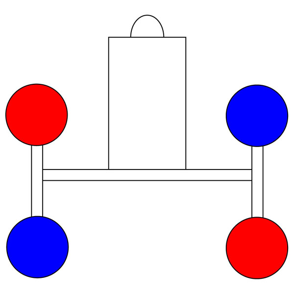
The 4 suction cups here are distributed across 2 vacuum circuits. Every vacuum circuit now has 2 suction cups. Here, 2 suction cups are marked in blue and 2 suction cups are marked in red.
On a properly configured 2-circuit vacuum lifting device, if a vacuum hose gets severed, nothing affects a nominal rating. It remains supported by the suction cups. However, a visual and/or acoustic warning should be issued. In addition, the affected vacuum control meter should display the danger area.
In 2008, at the Glasstec trade fair, we unveiled out Kombi 7411-DS3 vacuum lifter. That 4-circuit vacuum lifting device has four separate vacuum circuits. On a device of this kind, when the aforementioned case of a vacuum hose getting cut arises, only 25% of lifting power is lost, rather than the 50% lost on a 2-circuit vacuum lifting device. This device therefore needs fewer suction cups than a 2-circuit vacuum lifter.
We have also produced a short video of this, in which we try to illustrate what a 1-circuit, a 2-circuit and a 4-circuit vacuum lifter actually is. Using an old Kombi 7011-DS vacuum lifter with four suction cups, this video illustrates the differences.
Just click the link, and the video file will open on any Internet-capable PC.
-
What does a 2-circuit vacuum lifter signify?
Find this on YouTube:
Based on the example of an old Kombi 7011-DS vacuum lifter